Inspecting Tankless Gas Water Heaters
Tankless water heaters have become extremely popular and are replacing many hot water tanks. Almost all the new builds I inspect have these units. They are also being used to heat homes using radiant systems. There are two basic types of tankless units; condensing and non-condensing. Here is the difference between the two:
Condensing: Non-Condensing:
- EFFICIENCY Up to 96% 80%
- VENTING PVC Metal
- LOCATION Inside / Outside Inside / Outside
- MAINTENANCE Annual Service When Necessary
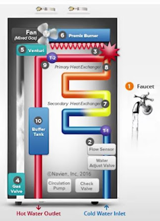
Inspection for either of these units is basically the same. The default temperature are normally set at 120 Degrees F. Both water pipes should be ¾”. The gas supply pipe would be ¾” also. It is also recommended that an expansion tank is installed between the unit and the cold water line. I have seen units that do not have expansion tanks. Refer to the manufacture, but most recommend one is installed. Clients always ask me if the tankless units will be adequate. Although it is not part of a visual home inspection, I like to give them a reference point. It is recommended that a 180,000 BTU unit is minimum for an average size house. Smaller houses, possibly for one or two occupants may be able to use a smaller unit (120-150,000 BTU). Consider this: a 200,000 BTU gas-fired tankless unit is able to raise the total water temperature 50 F at a maximum of 7.4 GPM. As a basic rule of thumb, each GPM subtracted from the total allows a 10-degree increase in water temperature. In this scenario, a 200,000 BTU water heater would be able to heat all of the water in a house at a 6.4 GPM flow rate to 110 F, and at a 5.4 GPM flow rate, would be heated to 120 F. Incoming water temperature will also effect this basic calculation. The sequence of operation for tankless gas water heaters:
1- When a hot water tap is opened, the tankless water heater detects the flow
2- The flow sensor activates to determine the amount of hot water needed
3- The igniter activates
4- The gas control valve opens to supply the correct amount of gas
5- The fan and venturi activate to provide the correct amount of gas and fuel
6- The premix burner ignites providing a flame to heat the water
7- Cold water is pre-heated in the secondary heat exchanger
8- Pre-heated water passes from the secondary to the primary heat exchanger
9- The unit determines outgoing set temperature and adjusts the flame to heat the water
10- Heated water moves to the buffer tank
11- Desired hot water amount delivered to the faucet
What should a home inspector be looking for?
- Both water lines should be ¾ “
- The Natural Gas pipe should be ¾”
- The Natural Gas pipe should be the first line past the meter connected to the unit
- The condensate drain should drain in an area where it will not come in contact with people or animals
- A Pressure Relief Valve should be placed as close to the unit as possible. (Many units have an internal high temperature shut-off switch. Check with the manufacture)
- The discharge pipe from the pressure relief valve should extend to an acceptable drain within 6 inches of the floor
- For horizontal vent pipe runs, slope the horizontal section upward toward the vent termination at a rate of 1 /4 in per foot
- Ensure that 3.0” of the exhaust pipe has been completely inserted into the vent collar
- Exhaust and intake air pipes must be supported at least every 4 ft
- The intake / exhaust vent should be higher than an anticipated snow line
- The vent run should not start with an elbow at the vent collar. Using an elbow directly at the collar will not allow for a tight seal between the appliances and vent pipe. A length of straight pipe must be used when starting the vent run
- Clearance above grade, veranda, porch, deck, or balcony = 12 inches
- Clearance to window or door that may be opened – 6 in for appliances ≤ 10,000 Btu, 9 in for appliances > 10,000 Btu and ≤ 50,000 Btu, 12 in for appliances > 50,000 Btu
- Clarence for non-direct venting (single pipe) = 4 ft below or to side of opening; 1 ft above opening
- These are the only approved vent piping: PVC/CPVC Schedule 40 or 80 (Solid Core) – UL1738 approved PVC or CPVC – Approved Polypropylene (PP) – Approved Stainless Steel (SS)
- Air intake and exhaust should be a minimum of 2” or increased to 3” depending on the length of the run
- For vent sized 2 inch –75 ft maximum run. A maximum of 6 elbows can be used which reduces the length of the pipe accordingly for each elbow used: Each 90° elbow equates to 8 linear ft of vent pipe reduction. Each 45° elbow equates to 4 linear ft of vent reduction
- For vent sizes 3 inch – 150 Ft Maximum run. A maximum of 8 elbows can be used which reduces the length of the pipe accordingly for each elbow used: Each 90° elbow equates to 5 linear ft of vent reduction. Each 45° elbow equates to 3 linear ft of vent reduction
- The use of a PVC or polypropylene concentric termination counts as 5 linear feet of vent
- For roof terminations: 12” min. clearance above highest anticipated snow level or grade, whichever is greater. Maximum of 24” above roof.
- The intake and exhaust pipes should be separated by 12-18 inches
- Most units have a factory-installed, 3-pronged (grounded) plug. The water heater can be plugged into any grounded electrical outlet nearby, as it requires only 2 – 4 Amps. It is not necessary to run a dedicated electrical line to the water heater
- Advise your client that the unit will have to be flushed periodically depending on usage. Valves located near both water lies should be installed that will allow for this procedure. Not performing this required maintenance will reduce the serviceable life of the unit.
- With regular maintenance and normal operation these units should have a 15-20 year serviceable life
Related Articles:
- Expansion Tanks on Hot Water Heaters
- Heat Pump Hot Water Heaters
- Gas Pipe Installation
- Inspecting Oil Tanks
Want To Learn More? Click HERE to Search Our Full Database Of Home Inspector Newsletters.